Showing posts with label Electronics. Show all posts

Thursday, November 11, 2021

RGB shelf lights

 Hi! At most I don't have much time to post here. But I'm trying))

Here is a combination of my KSN20 RGB controller and shelf light endpoint repeaters.

At first, final result:


RGB controller


Hi! I like decoration lights, so RGB controllers are "must have" devices for me =)
I decided to make module system, so for any light power I need only different type of repeaters instead of making new controller board for each purpose.

So this is main RGB controller board designed for my KSN20 CAN network:

Sunday, January 7, 2018

Another WS2812b VU Meter (Tiny version)

Hello friends!
About a month ago I bought several pieces of WS2812b LED strip. Why not make another VU meter?
I decided to make mini VU meter for single channel which can fit to CFL lamp base.


Saturday, January 6, 2018

Cheap LED string rework (220VAC to 12VDC)

Hi friends!
Before New Year I've searched for a multicolor LED strings to decorate my home. But there was a problem. All strings at our stores must be powered from mains 220VAC. But there are some places at home without mains power outlets due to safety and 12VDC only. And the other reason is poor quality of most these products. Some of them are really dangerous and can burn without any visible reason.
So I decided to make some rework of a cheap LED string.
Click on any photo for full size.

60+60 series LED's work with 12VDC supply

Tuesday, April 25, 2017

Thermal transfer paper DIY PCB test

Hi!
Some days ago I've got another pretty thing from Aliexpress: thermal transfer paper for PCB DIY.
After making some boards with 0.5mm traces with perfect quality, I decided to test capability of this paper and my printer (HP 1020). Main goal was to create home made PCB with 0.25mm traces and 0402 components =)
So here is a test board after etching in ferric chloride:


Left side: 0.33mm traces with ~0.3mm spacing. Right side: 0.25mm traces, ~0.2mm spacing, one 0603 and two 0402 components.

Let's have a close look (click for large images):


Close to perfect for home DIY! Link to Ali store if you're interested.

Sunday, September 11, 2016

Buck-Boost LED Driver (34063)

Hi all! Earlier this year I've made improved version of 34063 LED driver. This is combined buck-boost converter witout output voltage inversion. Now I have some time to describe it =)

Buck-Boost noninverting LED Driver 34063

Monday, August 22, 2016

9V multimeter powered from single AA battery

Hi! Another 9V battery was dead in my 830 multimeter. I've used this situation to make some modifications. I have a lot of half empty AA and AAA batteries, so I decided to power up multimeter from 1.1V (fresh AA/AAA have 1.5V).


Sunday, January 31, 2016

Driving MOSFET's in a cheap way

Hi all!
As you know MOSFET-s are definitely best choice for switching-mode applications. But in most cases they need a gate driver circuit to work properly (of course, if you don't want o make a heater =)). There are lots of driver IC's, but I decided to go another way and test simple discrete driver.

Few days ago I bought some BJT's: SS8050 and SS8550. they are fast (~150-200 MHz), have high collector current (0.7A continuous, 1.5A pulse). Vce is about 20V (most FET's Vgs value).


So I've made two drivers on a breadboard: N-FET low-side and N-FET high-side with bootstrap.


To drive MOSFET(Q1) 8050 and 8550 BJT's are connected as totem-pole emitter follower. I've tested these drivers with 5V signal source, so I've added an inverting level shifter (Q6, R26). If TL494 (for example) is used as control source there is no need in level shift in most case.

Load was 12V 21W auto lamp (~1.8A). MOSFET was without any heatsink. Control signal: square wave generator with PWM on TL7555 timer with output buffer (74HC04). Frequency: 2KHz to 70 KHz.

Saturday, January 17, 2015

74HC595 breakout board

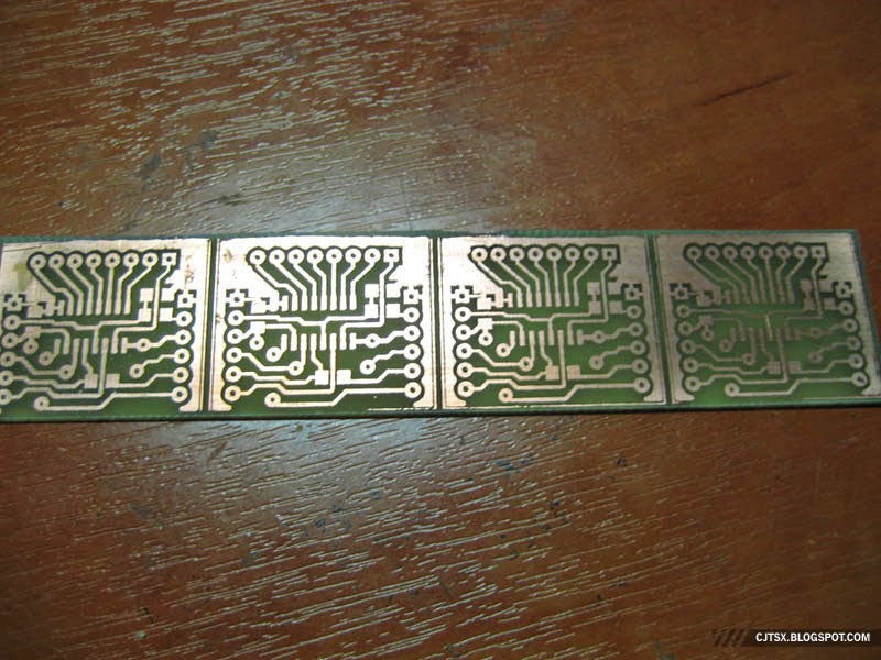
Recently I've bought a bunch of cheap 74HC595 shift register IC's. But SOIC case is not suitable for solderless breadboard. I didn't want to buy this IC's in a DIP case too, so I've made my own breakout board for them.
Single side PCB with 3 jumper wires on top side. Not so small as Adafruit's (for example), but easy to make with laser printer and iron. Supports daisy chain.


Etched PCB's

Monday, September 29, 2014

Cheap breadboard wires

When testing circuits on a breadboard or my modules, I often need jumper wires with non-standard length. Yes, there are packs of factory wires in shops, but why buy, when you can make them? =)


Saturday, September 27, 2014

Atmega8/48/88/168/328 EV-X2 board

Today I've made another MCU-based device: breadboard-like unit with Atmel Mega88 MCU core.


EV-X2 board with my USBASP connected

Device contains:

  • Built-in 5V supply (L78M05) for MCU
  • 3pcs 5V outputs for external devices
  • Onboard AVRISP socket
  • Reset button
  • Clamping zeners for ADC6 and ADC7 inputs
  • Switched I2C pull-up's (not exists on photos, I don't have dual DIP switches now, it will be installed later =( )


Wednesday, September 17, 2014

Open-source electronics calculator

Features

  • Calculator for MC34063 (all converter types)
  • Resistor voltage divider (simple with match finder and 3-element with pot trimmer)
  • Basic calculator (current, power, etc.)
  • LM2576 buck converter + Vout calculator
  • TL431 reference calculator + part match finder
  • Zener diode references and calculator
  • LED series resistor calc
  • Atmel MCU timer calculator
  • Voltage drop in a wire/cable
  • Parallel/series element connection
  • Resistor color band decoder
  • Reactive resistance (L/C) calculator


Build links and source code (Delphi 7) available on Google Code.
Browse build archives on Google Drive

Tuesday, September 2, 2014

DC-DC Boost LED driver (based on MC34063)

New update of my DC-DC boost LED driver (full story you can see here (in Russian)). Added output overvoltage protection (D2,D3) and D1 changed to Vishay 30BQ100. Also I've added simple amplifier for current-sense resistor, so it can be now 1W (1 Ohm for 700mA LEDs, 2 Ohm for 350 mA).

Inductor: 60 turns of 18AWG copper wire on T90-52 core (I've used inductor from dead ATX PSU).

Please note: There is no short-circuit protection for output!


Some other notes.

  • Overvoltage limiting 1W zener diodes D2 and D3 may be changed to single 0.5W zener for appropriate maximum output voltage. For example BZX55C47 for max. 47V output.
  • Maximum output power depends on primary power supply maximum load capability, current sense resistor R1, MOSFET Q1, inductor coil and flyback rectifier D1.
  • This circuit cupports max. 16V input (limit by MOSFET driver).
  • NCP3065/66 is more suitable for CC LED driving (lower feedback voltage) but I don't have them now for test.


Thursday, July 31, 2014

Simple precision rectifier

Some time ago I've assembled a simple circuit of full-wave precision rectifier to feed signal from 50Hz AC current transformer to Atmega ADC input.
Here this unit schematic:
(picture taken from from sound.westhost.com)

Everything was fine, except strong self-oscillation of first opamp on one of half-waves (after some time TL072 become hot!). Bypass D1 with a tiny 0805 SMD capacitor 560pF completely removed this "bug" =)

And at last I've changed opamp to LM358. No significant changes and distortions on output. D1,D2: 1N4148.
Opamp is powered +/- 15V.