About a month ago I bought several pieces of WS2812b LED strip. Why not make another VU meter?
I decided to make mini VU meter for single channel which can fit to CFL lamp base.

Ok, let's start. My meter must handle 3 frequency bands: low, middle and high. I chose Attiny24 MPU in small SO-14 case. Project contain 2 PCB's.
Board 1 - Schematics
Input is designed to handle 0.6Vp-p audio signal. First, input signal goes to two stage amplifier with AGC. Next signal splits to frequency bands with simple RC bandpass filters.
 |
| Board1 schematics. |
D7,D8 - PMLL4448
D1,D3-D6 - BAV23S
VT1 - BC846
Resistors & capacitors - 0805, except C2 - 1206
Board 2 - Schematics
At second PCB located 3 adjustable band amplifiers and MCU. Band amplifiers are needed due to scale low signal level after RC bandpass filters to 0-5V ADC range.
 |
| Board2 schematics |
 |
| Band amplifiers block |
I used op amps in small SO8 and SOT23 case. All PCB's are single side and suitable for DIY at home.
Assembly
Here is Board1 (flux not washed, it's a testing stage)

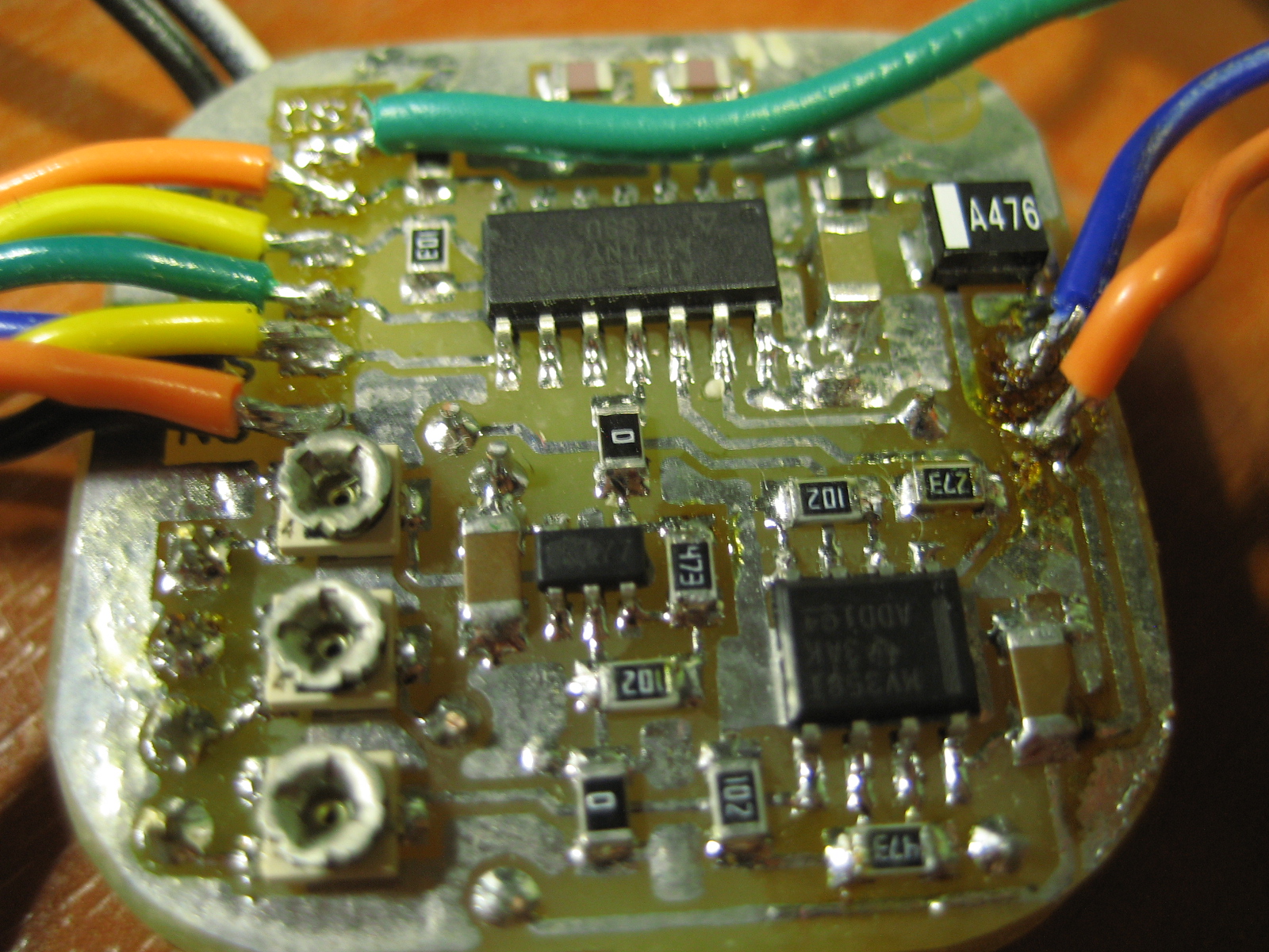
Board2. Wires at left - ISP connector, not needed after firmware upload =) Green wire at top - WS2812 data line.
 |
| Boards assembled |
 |
| CFL lamp base. VU meter enclosure =) |
Power
Project is powered 5V from mini DC-DC converter. Input range: 9-20VDC.
 |
| DC-DC and power capacitors |
 |
| Fit test =) Will be OK without ISP wires. |
There is several color mode support in firmware (see source code). Button is connected to MISO pin and ground.
- 3 color band VU
- Color gradient 1
- Color gradient 2
Please forgive my old laggy webcam, video freeze sometimes.
Files
- Schematics - Board 1, DipTrace 3
- Schematics - Board 2, DipTrace 3
- PCB layout - Board 1, DipTrace 3
- PCB layout - Board 2, DipTrace 3
- Firmware & source code (Attiny24, Atmel Studio 6.1)
No comments:
Post a Comment